
Electric actuators are devices that are used in the controlling and moving of control systems and mechanisms. They are connected through wire setups depending on the environment, actuators, and the power energy to operate. These energy sources include electric current or hydraulic pressure, which is converted into motion.
There are three major types of electric actuators namely; multi-turn actuators, quarter-turn actuators and linear actuators. This article demonstrates the method for the best practices to utilize relay boards to control the movement of linear actuators. There are 2-channel, 4-channel and 8-channel relay boards accessible and they all serve the same purpose. The main difference is what number of channels are usable. In this article, we will be consolidating the relay boards with our LC-066 Arduino Uno to hotshot their control capacities.
How relay boards are used to control linear actuators
The relays control the course in which the actuator moves. They work using current from the input source to enact an electromagnet. This electromagnet in turn pulls a switch that permits higher streams of current on the inverse side of the relay to stream. On the control side of the relays, one comes across a GND pin, a VCC pin and IN pins that are numbered from 1 to 8. The numbering of IN pins depends on the model of the relay. These relays need a lot of energy to stay active. This means that there is the need for a stable source of power, approximately a 5V power supply. In case there a lower or higher power supply, the Arduino will experience difficulties in driving the higher channel relay modules.
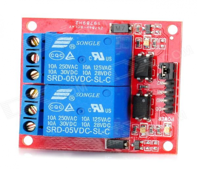 Figure 1: Relay board for Arduino
Typically, they can create a couple of hundred milliamps, which is sufficient to power a 2 channel relay module like the LC-200. This is however nowhere near enough to power an 8 channel relay module like the LC-202. In this article, we will be utilizing the 2 channel relay board as the one shown above in Figure 1. With respect to wiring the relay modules, there is a need to take after some straightforward steps. On the control side of the relay, first we have to create a connection between the 5V power supply with the VCC and GND pins. The next step is to connect the IN pin with the Arduino pin that corresponds to it. The relays will then be active after the IN pins are connected with the GND pins. On the relay side, there consists of three primary parts of every relay, terminals for three screws.
These terminals are normally known as the Normally Closed association (NC). The top most connection is called the Common association (COM). There is also the middle connection and the bottom most connection that is called Normally Open connection (NO). In cases no connections are made to the IN pin, the relay will connect between COM and NC terminals. If a connection is created between the IN pin and the 5V power source, the relay will connect between the COM and the NC terminals as well. Additionally, if a connection is created between the GND and IN pins the relay will unite between the COM and the NO terminals. At this point, everything is wired up correctly and basic coding using the Arduino Uno can be performed as demonstrated below in Figure 2.
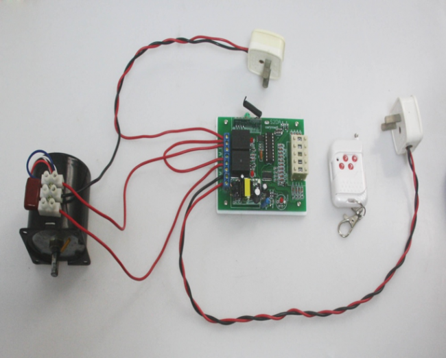 Figure 2: A fully connected 2 channel relay board